|
|
| ECM | 14.12.2003 |
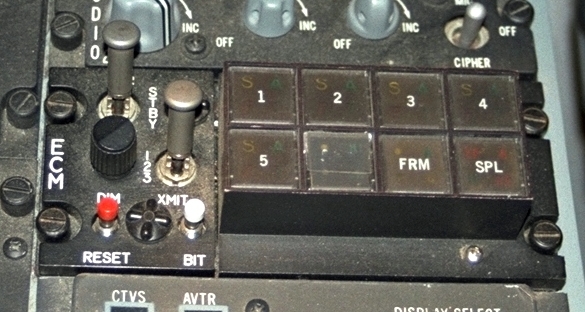
| The panel and his elements (Block 40/52, 50/52, MLU) |  |
| Element | Type | Position | Information |
|---|---|---|---|
| OPR | 3-Way switch | OPR | EPC on (operation) |
| STBY | ECM in standby-mode | ||
| OFF | ECM off | ||
| XMIT | 3-Way switch | 1 | ? |
| 2 | ? | ||
| 3 | ? | ||
| DIM | Rotary pot | 0 - ... | Dimmer control for brightness the ECM status lights |
| RESET | Button | - | ? |
| BIT | Button | - | Test all ECM lights in full illumination. |
| 1 | Button with 4-Status light |
CB (yellow) | ? |
| A (green) | ? | ||
| TN (red) | ? | ||
| SP (green) | ? | ||
| 2 | Button with 4-Status light |
S (yellow) | ? |
| A (green) | ? | ||
| F (red) | ? | ||
| T (green) | ? | ||
| 3 | Button with 4-Status light |
S (yellow) | ? |
| A (green) | ? | ||
| F (red) | ? | ||
| T (green) | ? | ||
| 4 | Button with 4-Status light |
S (yellow) | ? |
| A (green) | ? | ||
| F (red) | ? | ||
| T (green) | ? | ||
| 5 | Button with 4-Status light |
S (yellow) | ? |
| A (green) | ? | ||
| F (red) | ? | ||
| T (green) | ? | ||
| Button with 4-Status light |
HI (green) | ? | |
| A (green) | ? | ||
| I (green) | ? | ||
| LO (green) | ? | ||
| FRM | Button with 4-Status light |
C (yellow) | ? |
| A (green) | ? | ||
| II (green) | ? | ||
| F (red) | ? | ||
| SPL | Button with 4-Status light |
RP (red) | ? |
| A (green) | ? | ||
| IC (red) | ? | ||
| SM (red | ? |
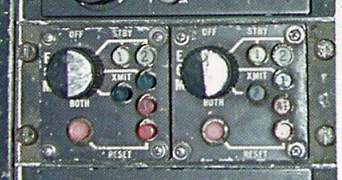
| The panel and his elements (Block 25, 30/32) | |
| Element | Type | Position | Information |
|---|---|---|---|
| ECM 1 | Rotary switch (4x45 deg) |
OFF | ? |
| STBY | ? | ||
| XMIT | ? | ||
| BOTH | ? | ||
| STBY 1 | Button with status light? |
1 (white) | ? |
| STBY 2 | Button with status light? |
2 (white) | ? |
| XMIT 1 | Button with status light? |
1 (green) | ? |
| BOTH 2 | Button with status light? |
2 (green) | ? |
| A1 | Button with status light? |
A1 (red) | ? |
| RESET 1 | Button with status light? |
(red) | ? |
| RESET 2 | Button with status light? |
(red) | ? |
| ECM 2 | Rotary switch (4x45 deg) |
OFF | ? |
| STBY | ? | ||
| XMIT | ? | ||
| BOTH | ? | ||
| STBY 1 | Button with status light? |
1 (white) | ? |
| STBY 2 | Button with status light? |
2 (white) | ? |
| XMIT 1 | Button with status light? |
1 (green) | ? |
| BOTH 2 | Button with status light? |
2 (green) | ? |
| A1 | Button with status light? |
A1 (red) | ? |
| RESET 1 | Button with status light? |
(red) | ? |
| RESET 2 | Button with status light? |
(red) | ? |
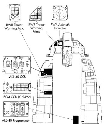
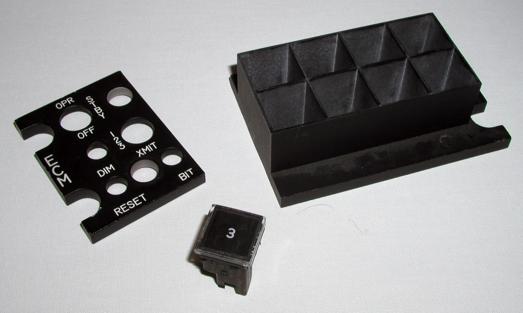
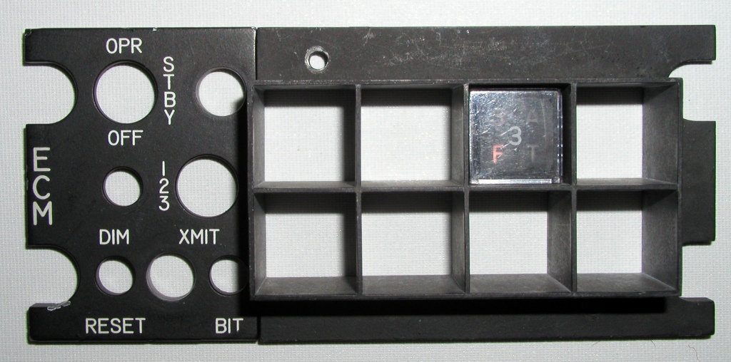
| The ECM growth panel | |
| Drawings from the Electronic Countermeasures Stowage Panel | |
|
|
| Pictures from the Electronic Counter Management Stowage Panel | |
| ECM | ||
 Block 40/42, 50/52, MLU |
 Block 40/42, 50/52, MLU |
 Block 40/42, 50/52, MLU |
 Block 40/42, 50/52, MLU |
 Block 40/42, 50/52, MLU |
 Block 25, 30/32 |