
|
|
| Elec | 28.07.2003 |
|
|
Das Panel und seine Elemente (Block 40/42 aktuell, 50/52) |
|
|
Das Panel und seine Elemente (Block 25, 30/32, 40/42 alt, MLU) |
|
|
Das Panel und seine Elemente (Block 25 alt) |
|
|
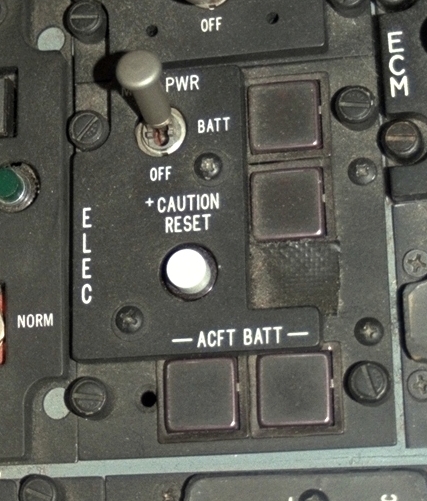
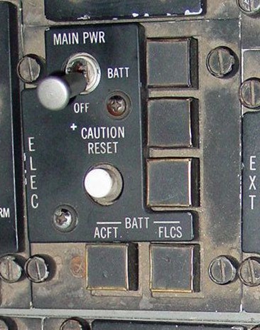
Bilder des Electronic Panels |
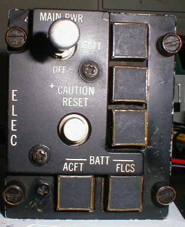
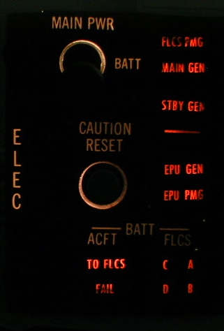
| Das Panel und seine Elemente (Block 40/42 aktuell, 50/52) |  |
| Element | Type | Position | Information |
|---|---|---|---|
| MAIN PWR | 3-Way switch | MAIN PWR | Connects external power or the main generator to the electrical system and enables standby generator. Determines function of FLCS PWR TEST switch. If ac power is not available, connects aircraft battery to the battery buses. |
| BATT | Connects aircaft battery to the battery buses, disconnects main generator or external power, resets main generator, disables standby generator and determines function on FLCS PWR TEST switch. | ||
| OFF |
Flight: Disconnects main generator from electrical system and disables standby generator. Ground: Disconnects all main generator or external power from the aircraft electrical system and disables standby generator. Disconnects the aircraft battery from the battery buses. Canopy operation and FLCS battery trickle charge are available after engine shutdown. |
||
| CAUTION RESET | Button | - | Resets ELEC SYS caution light and clears MASTER CAUTION light for future indications. Resets main and standby generators. Resets overload protection unit for the nonessential ac bus and the nacelle ac bus. |
| Status light | 2-Status light (amber) |
FLCS PMG |
Flight: FLCS PMG is not supplying power to any FLCS branch. Ground: FLCS PMG power is not available at one or more FLCS branches. Light is delayed 60 seconds after initial NLG WOW. |
| MAIN GEN | Indicates that external power or main generator not connected to one or both nonessential ac buses. | ||
| Status light | 2-Status light (amber) |
STBY GEN | Indicates standby generator power is not available. |
| - | |||
| Status light | 2-Status light (amber) |
EPU GEN | Indicates the EPU has been commanded on but the EPU generator is not providing power to both essential ac buses. The light will not function with the EPU switch in OFF (WOW) and the engine is running. |
| EPU PMG | Indicates the EPU has been commanded on but EPU PMG power is not available to all branches of the FLCS. | ||
| ACFT BATT | 2-Status light (amber) |
TO FLCS |
Flight: Indicates battery bus is supplying power to one or more FLCS branches and voltage is 25V or less. Ground: Indicates battery bus is supplying power to one or more FLCS branches. |
| FLCS RLY | Indicates that voltage on one or more of the four FLCC branches connected to the aircraft battery is inadequate (below 20V) or that one or more FLCS branches are not connected to the battery. | ||
| ACFT BATT | Status light (amber) |
FAIL |
Flight: Indicates aircraft battery failure (20V or less). Ground: Indicates aircraft battery or battery charger failure. Light in delayed 60 seconds after MLG WOW. |
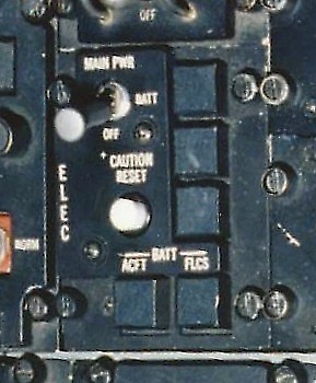
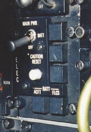
| Das Panel und seine Elemente (Block 25, 30/32, 40/42 alt, MLU) | |
| Element | Type | Position | Information |
|---|---|---|---|
| MAIN PWR | 3-Way switch | MAIN PWR | Connects external power or the main generator to the electrical system and enables standby generator. Determines function of FLCS PWR TEST switch. If ac power is not available, connects aircraft battery to the battery buses. |
| BATT | Connects aircaft battery to the battery buses, disconnects main generator or external power, resets main generator, disables standby generator and determines function on FLCS PWR TEST switch. | ||
| OFF |
Flight: Disconnects main generator from electrical system and disables standby generator. Ground: Disconnects all main generator or external power from the aircraft electrical system and disables standby generator. Disconnects the aircraft battery from the battery buses. Canopy operation and FLCS battery trickle charge are available after engine shutdown. |
||
| CAUTION RESET | Button | - | Resets ELEC SYS caution light and clears MASTER CAUTION light for future indications. Resets main and standby generators. Resets overload protection unit for the nonessential ac bus and the nacelle ac bus. |
| Status light | 2-Status light (amber) |
FLCS PMG |
Flight: FLCS PMG is not supplying power to any FLCS branch. Ground: FLCS PMG power is not available at one or more FLCS branches. Light is delayed 60 seconds after initial NLG WOW. |
| MAIN GEN | Indicates that external power or main generator not connected to one or both nonessential ac buses. | ||
| Status light | 2-Status light (amber) |
STBY GEN | Indicates standby generator power is not available. |
| - | |||
| Status light | 2-Status light (amber) |
EPU GEN | Indicates the EPU has been commanded on but the EPU generator is not providing power to both essential ac buses. The light will not function with the EPU switch in OFF (WOW) and the engine is running. |
| EPU PMG | Indicates the EPU has been commanded on but EPU PMG power is not available to all branches of the FLCS. | ||
| ACFT BATT | 2-Status light (amber) |
TO FLCS |
Flight: Indicates battery bus is supplying power to one or more FLCS branches and voltage is 25V or less. Ground: Indicates battery bus is supplying power to one or more FLCS branches. |
| FAIL |
Flight: Indicates aircraft battery failure (20V or less). Ground: Indicates aircraft battery failure, cell voltage inbalance or overheat condition. Light in delayed 60 seconds after MLG WOW. |
||
| FLCS BATT | 4-Status light (amber) |
C | Indicate the FLCS battery C is discharging. |
| A | Indicate the FLCS battery A is discharging. | ||
| D | Indicate the FLCS battery D is discharging. | ||
| B | Indicate the FLCS battery B is discharging. |
| Das Panel und seine Elemente (Block 25 alt) | |
| Element | Type | Position | Information |
|---|---|---|---|
| MAIN PWR | 3-Way switch | MAIN PWR | Connects external power or the main generator to the electrical system and enables standby generator. Determines function of FLCS PWR TEST switch. If ac power is not available, connects aircraft battery to the battery buses. |
| BATT | Connects aircaft battery to the battery buses, disconnects main generator or external power, resets main generator, disables standby generator and determines function on FLCS PWR TEST switch. | ||
| OFF |
Flight: Disconnects main generator from electrical system and disables standby generator. Ground: Disconnects all main generator or external power from the aircraft electrical system and disables standby generator. Disconnects the aircraft battery from the battery buses. Canopy operation and FLCS battery trickle charge are available after engine shutdown. |
||
| CAUTION RESET | Button | - | Resets ELEC SYS caution light and clears MASTER CAUTION light for future indications. Resets main and standby generators. Resets overload protection unit for the nonessential ac bus and the nacelle ac bus. |
| GEN | 2-Status light (amber) |
? | ? |
| ? | ? | ||
| BAT | 2-Status light (amber) |
? | ? |
| ? | ? |
| Bilder des Electronic Panels | |
| Elec | ||
 40/42c, 50/52 |
 25, 30/32, 40/42o, MLU |
 25, 30/32, 40/42o, MLU |
 25, 30/32, 40/42o, MLU |
 25, 30/32, 40/42o, MLU |
 25, 30/32, 40/42o, MLU |
|
|
(c) by Martin "Pegasus" Schmitt | |